
- Pickit 3 connection how to#
- Pickit 3 connection install#
- Pickit 3 connection serial#
- Pickit 3 connection drivers#
- Pickit 3 connection full#


Pickit 3 connection drivers#
Pickit 3 connection serial#
The connector uses two device I/O pins and the reset line to implement in-circuit debugging and In-Circuit Serial Programming™.
Pickit 3 connection full#
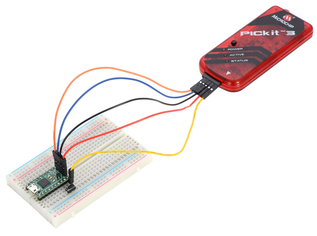
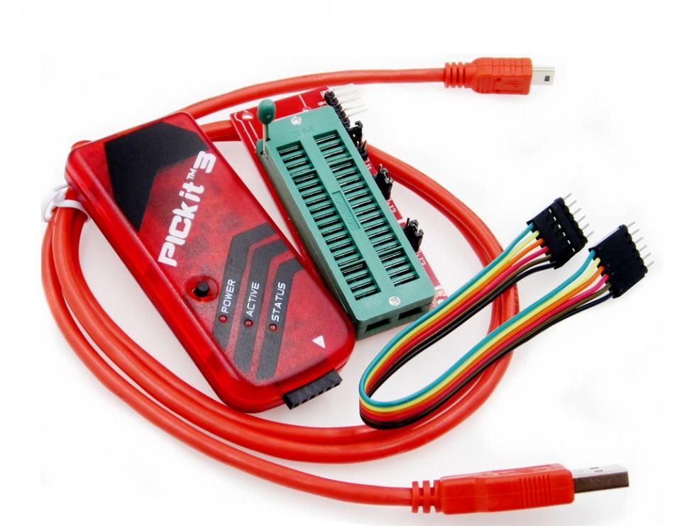
The MPLAB PICkit3 is connected to the design engineer's PC using a full speed USB interface and can be connected to the target via an Microchip debug (RJ-11) connector (compatible with MPLAB ICD 2, MPLAB ICD 3 and MPLAB REAL ICE). The MPLAB PICkit3 allows debugging and programming of PIC® and dsPIC® Flash microcontrollers at a most affordable price point using the powerful graphical user interface of the MPLAB Integrated Development Environment (IDE). Microchip's PICkit3 In-Circuit Debugger/Programmer uses in-circuit debugging logic incorporated into each chip with Flash memory to provide a low-cost hardware debugger and programmer. PICkit3 In-Circuit Debugger, Programmer-To-Go function Description Speech / Image Recognition / AI Cameras.In the pictures below you will find examples of connecting the PICkit with microcontrollers. The PGC from the PICkit must be connected to the RB6/T1OSO/T1CKI/ PGC which corresponds to the pin 12.The PGD from the PICkit must be connected to the RB7/T1OSI/ PGD pin, which corresponds to the pin 13.(Some microcontrollers have more than 1 power pin). The VSS (or in the GND power bus) from the PICkit must be connected to VSS which corresponds to the pin 5 .Check that the PGC, PGD lines are okay and check you made the proper connection PICkit3 users guide recommended. If you have another working PICkit3, you could try to manually reprogram the faulty unit. (Some microcontrollers have more than 1 power pin). Please check your connections to the Target Device. The VDD (or in the 5V+ power bus) from the PICkit must be connected to VDD which corresponds to the pin 14 of the microcontroller.The MCLR from the PICkit must be connected to the RA5/ MCLR/Vpp pin, which corresponds to the pin 4 of the microcontroller.The green arrows indicate the pins that can be connected to the power bus. The red arrows indicate the pins that must be connected near the microcontroller. This pins from the PICkit must be connected to the same pins of the microcontroller (for example, the PIC16F628A is pictured below). To find out which is which, refer to the following images.īoth images were taken from the PICkit 3 and PICkit 4 User Guides, respectively. They have to be 5 male-male units and at least 2,5cm long. If the microcontroller is placed in a breadboard, then I recommend that you connect them with jumper cables o wires like ones below.
Pickit 3 connection how to#
How to connect PICkit in a Breadboard? Use Jumper Cables Previously the operator had to visually identify each part on a pallet, and press the right. The system is used to produce 60 parts per day, out of which 41 are unique in shape. Is the microcontroller connected to a breadboard (left) or to a PCB (right)? Doosan Industrial Vehicle utilizes Pickit L-HD as eyes for a polishing robot for detecting a vehicle counterweight on a conveyor. Notice that PICkit 3 uses mini-USB-B and PICkit 4 uses micro-USB-B. Connect the PICkit to the computer with the included USB cable.

Pickit 3 connection install#
IIRC AVRdude supports the PICkit 2, and if you use Microchips standalone PICkit 3 utility (see below), it will install PICkit 2 emulation firmware into your PICkit 3, which AFAIK is then good enough for AVRdude to see it. If you have the PICkit 3, it will work equally good. Re: programming ATMEGA328p using PICKIT3. I will use for this tutorial the PICkit 4. Full-speed USB support using Windows standard drivers.


 0 kommentar(er)
